Application of Time-of-Flight Technology for Mobile Robot Perception and Navigation

Faculty of Automation and Computer Science
Technical University of Cluj-Napoca
Cluj-Napoca, Romania
popa.la.ioan@student.utcluj.ro, levente.tamas@aut.utcluj.ro

Demo Videos

Navigation Demo

Live Navigation - Real-time robot navigation with ROS

Simulator Demo

ROS Simulator - Navigation testing in simulation

Mapping Demo

Live Mapping - Environment mapping (3x speed)

Localization Demo

Monte Carlo Localization - AMCL particle filter (3x speed)

Robotic Platform Block Diagram

System Architecture: Mobile robot platform integrating Sphero RVR, NVIDIA Jetson Nano, and Analog Devices Time-of-Flight depth camera for autonomous navigation using ROS

Presentation Slides

Slide 1 of 18

Abstract

This paper presents a comprehensive exploration of mobile robot control and navigation, specifically within the domain of Wheel Mobile Robots, with a primary focus on the integration of Time of Flight technology. Leveraging Analog Devices' AD-96TOF1-EBZ kit for depth perception, the study investigates robotic mechanics, analyzes cognition structures, and implements localization, mapping, and navigation strategies. The research highlights key contributions, including the development of Robot Operating System support for the newly released Sphero Rover, providing crucial odometry data for the navigation system. Time of Flight technology is employed for real-time embedded applications, showcasing its efficacy in 2D depth perception, mapping, and localization through the Monte Carlo Localization algorithm. The paper details the architecture of the system, featuring the operation of multiple nodes on an NVIDIA Jetson Nano, where processes efficiently run on the embedded GPU. Testing scenarios involve navigating congested spaces, avoiding obstacles, and recovering from collisions, highlighting the practical use of Time of Flight technology in real-world settings.

Index Terms: Time-of-Flight(ToF), Mobile Robot Navigation, Robot Operating System (ROS), Embedded systems, Monte Carlo Localization, Machine Vision

I. Introduction

This research explores mobile robot control and navigation methodologies, particularly within the realm of Wheel Mobile Robots (WMR). Emphasizing the integration of perception capabilities, the project employs Time of Flight (ToF) technology, specifically Analog Devices' AD-96TOF1-EBZ development kit, for depth perception. The objectives encompass understanding robotic mechanics, analyzing cognition structures, and implementing localization, mapping, and navigation strategies. This study aims to showcase the efficacy of ToF technology in real-world scenarios, particularly in navigating industrial environments. The functional requirements involve scanning surroundings, constructing maps, and navigating them to user-imposed goals. Development and testing were conducted within the Robot Operating System (ROS) [1].

A. Mobile Robots

The primary focus in mobile robot design is to control mechanical components using perception capabilities derived from various sensor data and a cognitive structure processing this information. The main objective is to enhance navigation skills, encompassing trajectory planning, self-localization, perception, and the generation of signals for actuators to achieve desired odometry [2]. In the context of locomotion, this paper further concentrates on mobile robots. These robots navigate partially unknown scenarios, adapting to dynamic entities in their surroundings [3]. The discussion pivots around general kinematics and locomotion, forming the foundation for exploring motion control, localization, mapping, and navigation/planning methods. Methods integral to these considerations are expounded in [4]. This presents an overview of papers encompassing decision-making, control, and navigation, exploring various aspects specific to wheeled mobile robots.

B. Time-of-Flight Technology

In current robot navigation applications, vision-based techniques play a crucial role in perceiving spatial surroundings. Among various sensors used for motion planning and obstacle avoidance, ToF technology [5] stands out for its simplicity, efficiency, and speed in depth perception. The foundational principles and physical laws of ToF technology are detailed in [6] and [7], while calibration, experimental testing, and applications are covered in [8]. A ToF device consists of a charge-coupled device (CCD) camera and a modulated light-emitting projector. The CCD camera receives reflected light from objects, transforming it into electrical current signals proportional to its intensity. The modulating source produces the original light signal. The aims is to measure the time it travels on its round trip by computing the phase shift.

ToF Data Acquisition

Figure 1: Data acquisition structure for ToF camera [6]

A general scheme of data acquisition is shown in Figure 1. All pixels corresponding to the image are sampled at the same time, so the conversion and computational steps are done separately. Analog Devices (ADI) offers an integrated solution for ToF applications, the ADDI9036 [7] signal processor, which is an integrated circuit able to drive the laser transmitting diode, convert the received signal and extract the output necessary for computing the depth information, the phase shift. The depth information extracted is given by:

depth = (c · ΔT) / 2 = (c / 2) · (Tmod · φ) / (2π) = c / (4π · fmod) · φ

, fmod is the modulation frequency and c is the speed of light.

The versatility of ToF technology in mobile robotics spans object detection through shape matching, point cloud processing, and scene segmentation. This versatility, coupled with its reliability, positions ToF technology as an excellent tool for perception building, as exemplified in [9], highlighting low-cost, modular design, and rich sensor capabilities, a valuable reference for diverse ToF applications. ToF devices offer a compact depth perception solution, functioning effectively in varying light conditions due to their inherent capacity to reject environmental light source variations.

II. Localization and Navigation Strategies

Navigation encompasses the intelligent techniques of mapping, positioning, motion control, and planning to guide a mobile robot within its environment towards a target position [10]. The process involves global navigation, requiring prior knowledge for goal-reaching and local navigation, dynamically identifying environmental conditions and establishing positional relationships among elements [11]. The latter paper distinguishes global navigation methods, discussing the application of A* and Dijkstra algorithms for global path-finding and local navigation, commonly utilizing Lidar devices.

In [12], the authors compare pose estimation algorithms based on wheel, visual, and LiDAR odometry, along with Ultra-Wideband radio signals, all fused with IMU data, highlighting LiDAR odometry's consistent performance. Path planning algorithms, discussed in [13], span classical to reactive approaches for navigation in known and unknown environments. The overarching goal is to enable autonomous and effective robot maneuvering in complex environments.

Research in [14] addresses the challenge of handling uncertainty in sensor data for enhanced robot localization. It introduces an Extended Kalman Filter (EKF) that combines odometry with Ultra-WideBand ToF measurements and camera data from marker detection. The evaluation of this fusion system is conducted in a real-world environment using a dedicated differential robot, yielding promising results. Another version of an EKF-based state estimation algorithm [15] proposes an approach to overcome limitations by integrating data from a low-cost IMU and a ToF camera.

Machine intelligence, including rule-based techniques, behavior-based algorithms, and neural networks [16], integrates multi-sensor signals, as seen in [17], showcasing sensor fusion for safe and efficient navigation using wheel odometry, laser scanning, and RGB images. This approach aligns with current research, aiming to fuse odometry and depth data for mapping and navigation in unknown environments, particularly focusing on path planning using cost maps among different navigation strategies.

During the implementation stage, the focus will be on utilizing the IMU data from the Sphero RVR and integrating it with the depth information provided by the ToF module, building upon the concepts and ideas presented in this chapter.

III. Materials and Methods

A. Robotic platform

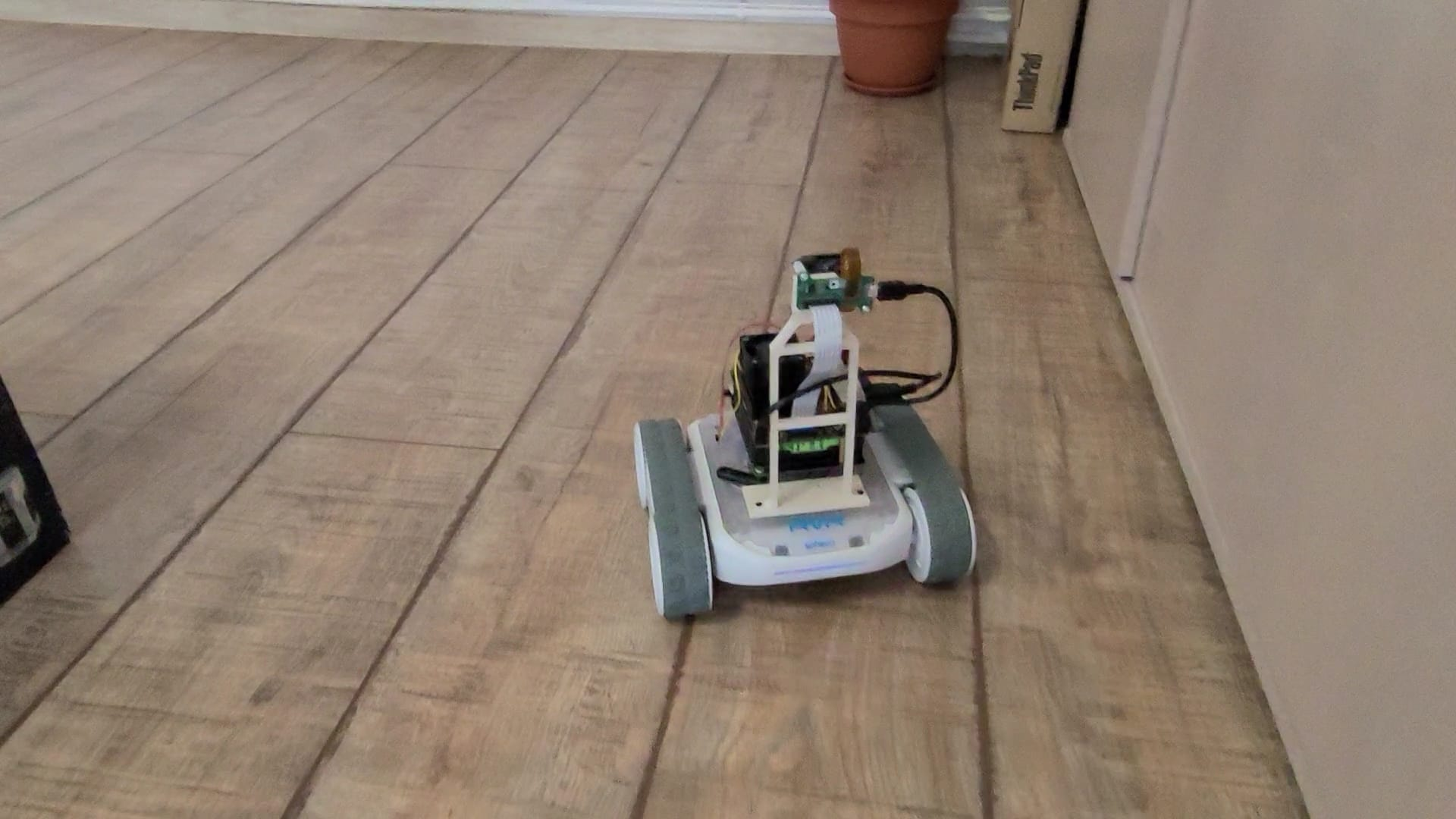
The Sphero RVR, designed for educational and research purposes, provides an interactive and flexible platform for diverse mobile robotics projects, with a focus on simplicity in design and available software applications and resources [18]. Featuring a four-wheel, differential-driven design with continuous tracks for stability on uneven terrain.

The robot integrates onboard sensors designed to measure its internal states, including relative position or velocity, as well as vision-based sensors: IMU (Inertial Measurement Unit): measures robot orientation on each axis (pitch, roll and yaw); Accelerometer: X,Y,Z measurements; Velocity sensor: linear velocities on X,Y; Gyroscope: angular velocities of X,Y,Z; Encoder: angular velocities for the wheels.

Sphero RVR Axis

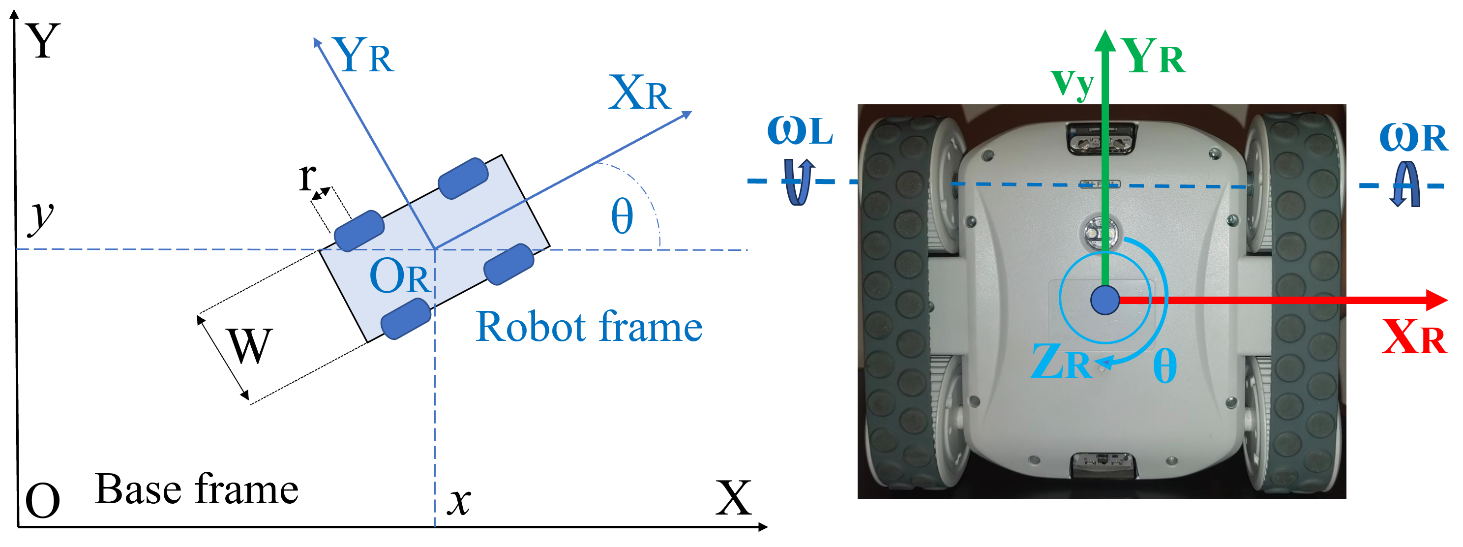
Figure 2: Sphero RVR axis system and drive

Regarding the rover's control, a key aspect to discus is the differential drive. The Forward Kinematics can be described considering the simplified robot geometry from Figure 2. Consider the width of the robot W, the radius of the wheels r, and angular velocities of the right ωR and left ωL wheels. We then describe the relationship of the linear and angular velocities with respect to the robot frame:

ξ̇R = f(r, W, ωR, ωL) = [r/2, r/2; r/W, -r/W] · [ωR; ωL]

, derived from kinematic equations in [19].

The RVR robot's kinematics rely on differential driving, with the front wheels propelling and the rear wheels ensuring stability (discussed in Chapter I-A). In motion control, our focus is on inverse kinematics, converting wheel angular velocities into the robot's pose. Wheel velocities, controlled by applied voltages, serve as inputs, following the relationship derived from forward kinematics.

Figure 2 illustrates possible displacements and rotations around the robot's axis. Notably, movement along the X-axis necessitates a change in orientation θ, classifying the Sphero RVR as a non-holonomic robot capable of controlling movement on the Y-axis and rotation independently.

The differential drive control logic is implemented in the software platform, laying the groundwork for deploying packages, developing position control, and testing the final solution.

The application interface communicates with the hardware platform through a UART connection, enabling sensor reading and actuator manipulation. All functionalities are part of the Sphero RVR software development kit (SDK)1, available on the Sphero RVR git repository. Changes were made for communication with the Jetson Nano board via UART.

The SDK, based on event-driven programming, responds to events like velocity commands through handling functions. It includes controllers for the driving structure, such as heading and speed control or driving to a goal position.

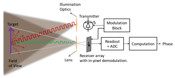
B. Analog Devices ToF Module

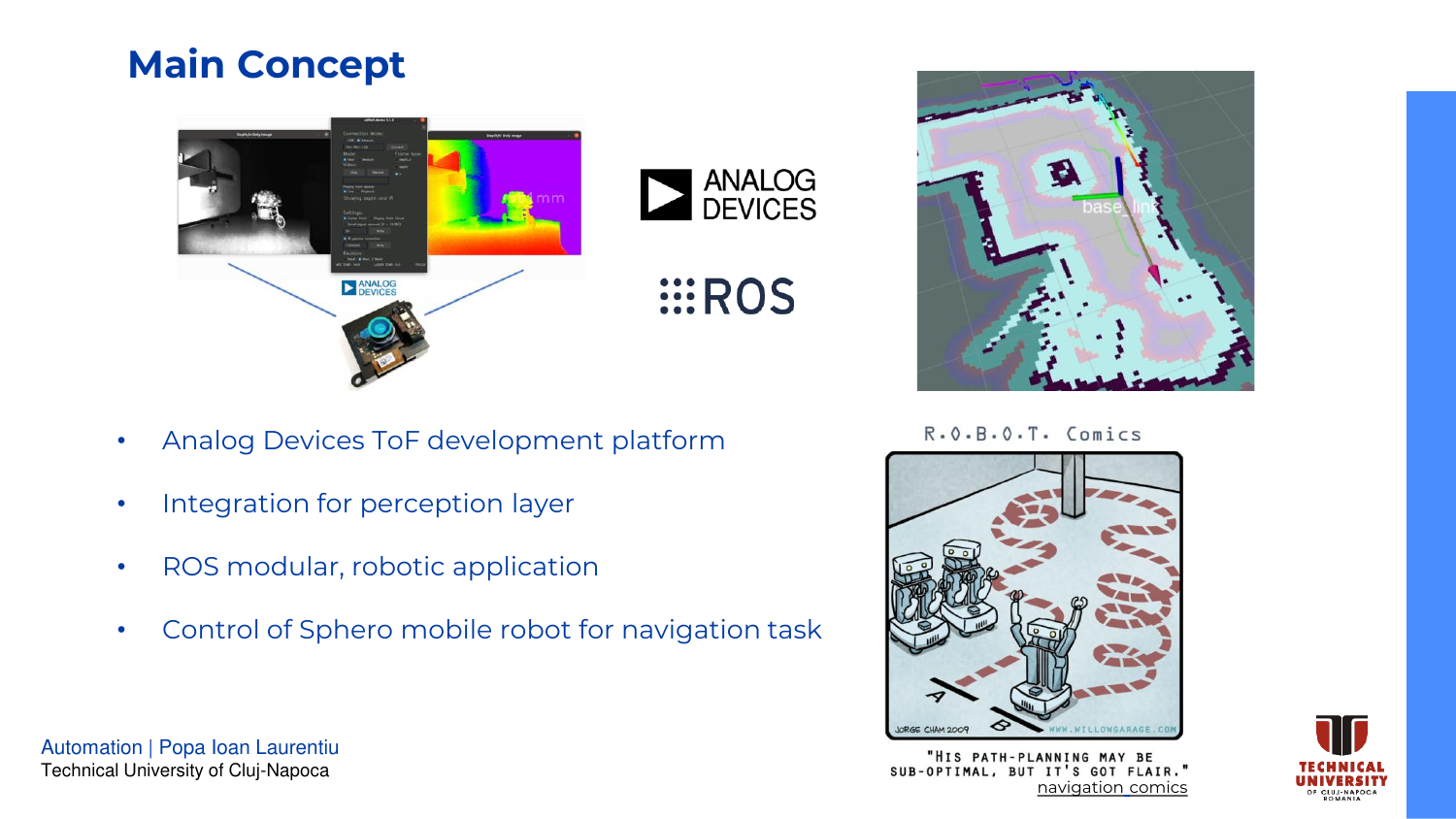
The mobile robot platform is enhanced by integrating the ADI ToF module, known as AD-FXTOF1-EBZ. The module supports standalone applications, and integrates with libraries like OpenCV, ROS, and Point Cloud Library.2

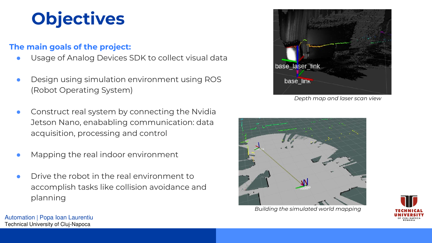
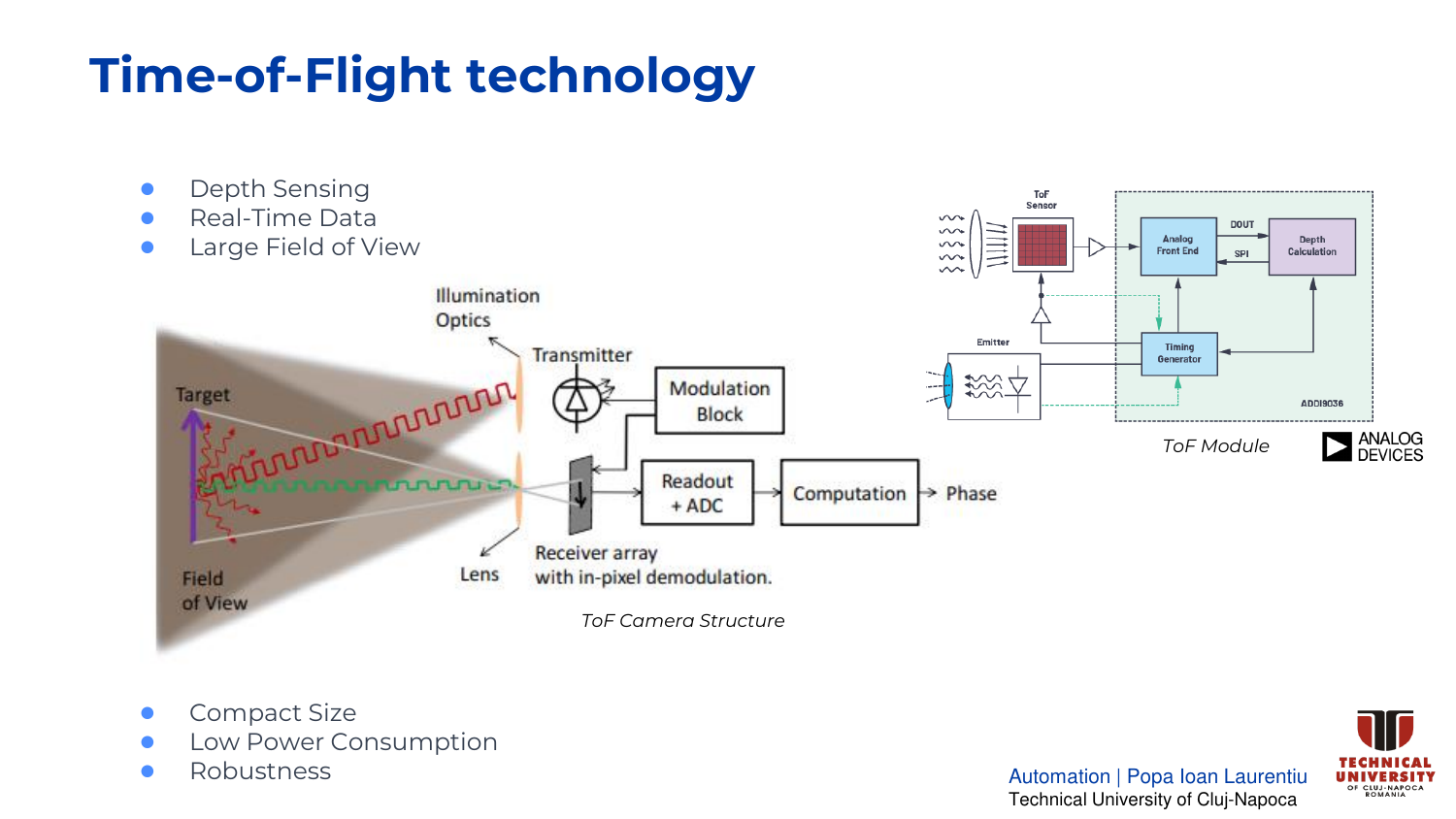
For robot perception, the AD-FXTOF1-EBZ module extracts vision data, such as depth maps, infrared images, or 3D point clouds. This data serves two main purposes: mapping and localization, by extracting features and creating an occupancy grid and object detection, by matching online recorded data with stored mapping. The theoretical background is detailed in Chapter I-B, emphasizes its depth extraction capability.

The implementation uses the latest provided Linux image to flash the SD card that will boot on the Jetson Nano. A detailed documentation on the setup and software available for development at found on the guideline page.3 The ROS Noetic framework was later installed on the Kuiper Linux.

C. Proposed Solution. Software Integration

This research creates a robotic platform by integrating the Sphero RVR mobile robot with ADI ToF technology for intelligent perception, self-localization, mapping, and navigation within a specific environment.

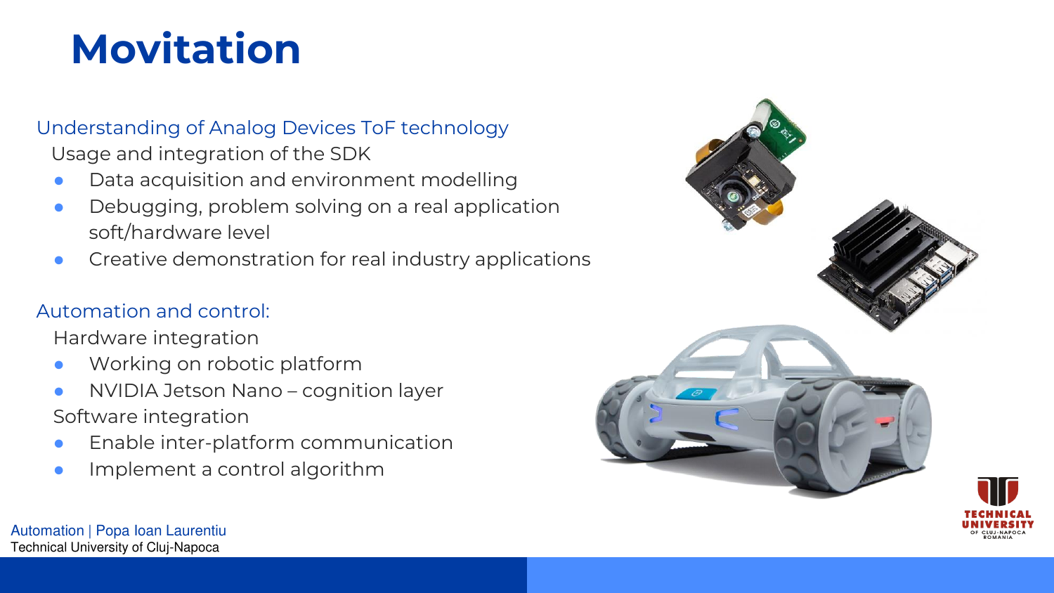
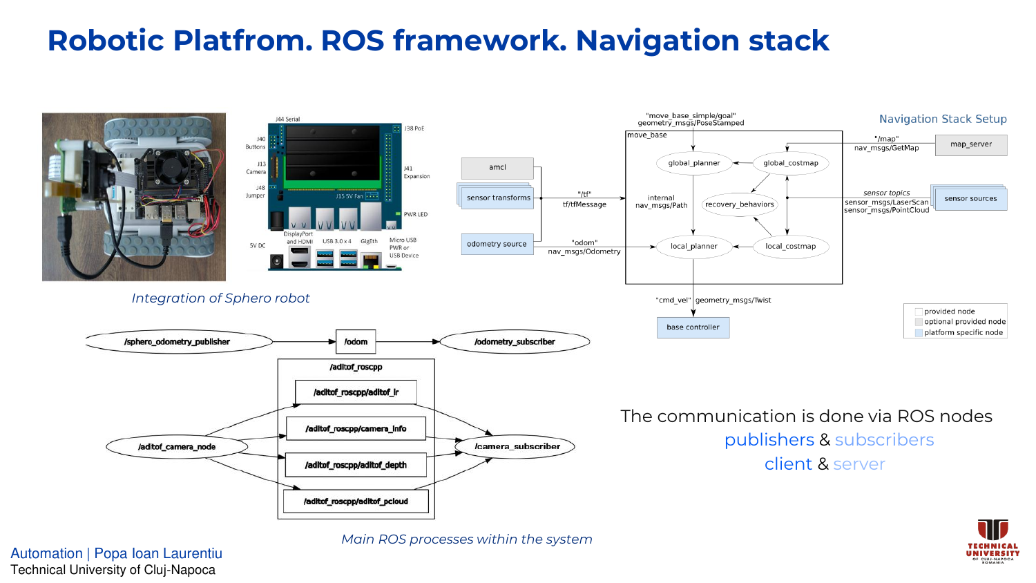
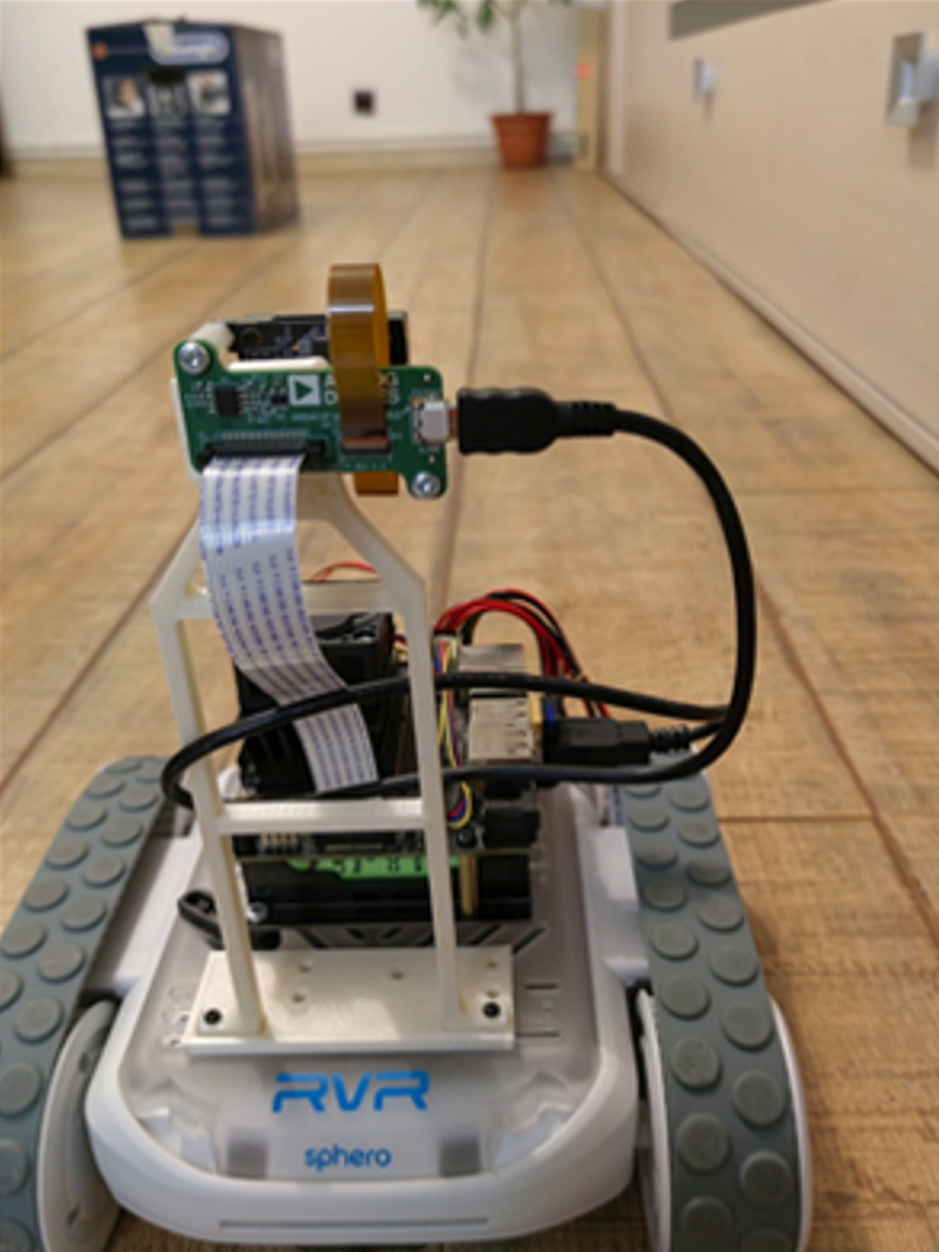
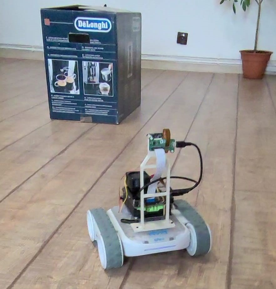
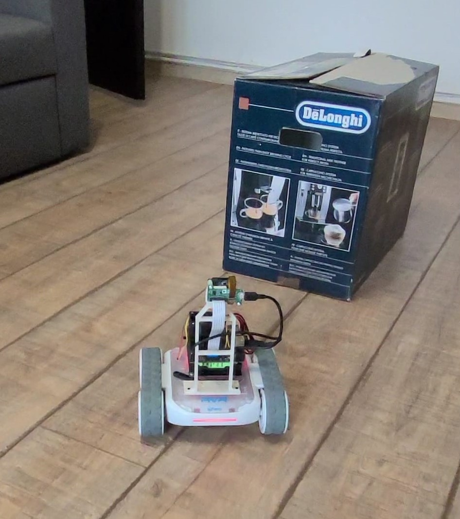
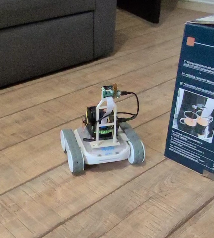
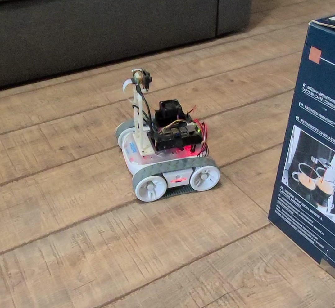
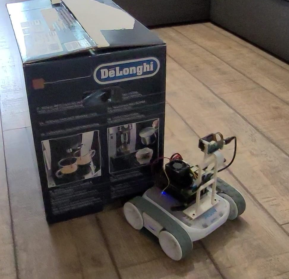
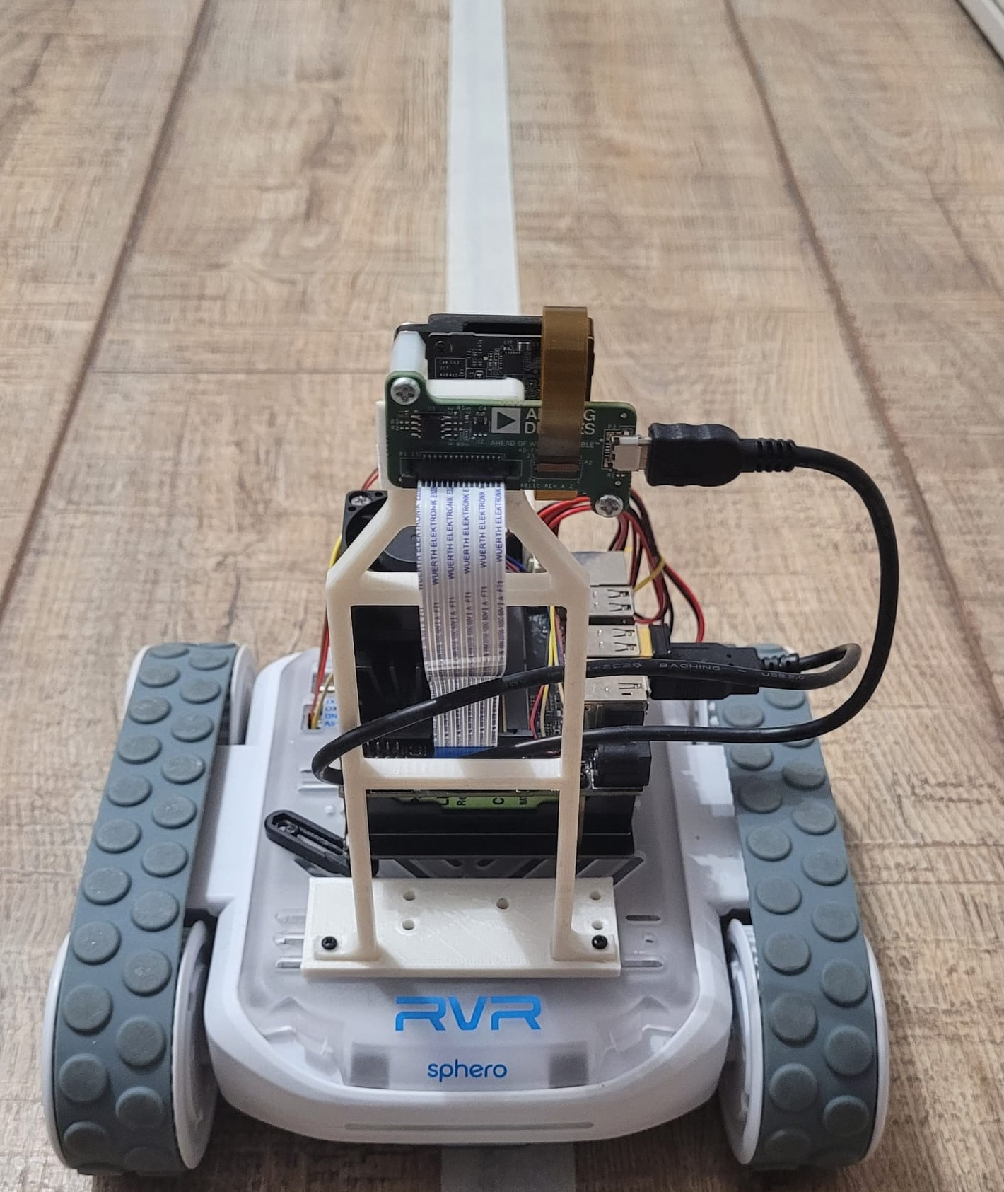
The design includes both hardware component integration and software architecture. The main hardware components (Figure 3) used for this task include: (a) The Sphero RVR: including all on board sensors and actuators, (b) Nvidia Jetson Nano board: processing unit for cognition functions, (c) ADI ToF Module AD-FXTOF1-EBZ: integrated module capable of both data acquisition and processing, and an Uninterruptible Power Supply module for Jetson Nano.

Hardware Components

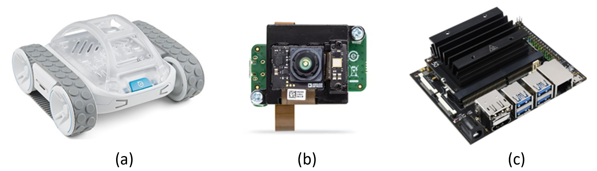
Figure 3: Hardware components

The integration relies on the ROS framework to facilitate communication between different software platforms, ensuring simultaneous data flow from sensors, and transmitting processed control signals back to the robot's actuating system. The Sphero SDK facilitates sensor reading and actuator control, augmented by an ROS node for publishing relative position estimates and subscribing to data from the camera module. The navigation master computes global position estimates and guides the robot toward its target pose, dividing actions into local tasks like trajectory following, collision avoidance, and self-checking current location based on visual input.

The Sphero SDK, operating on an event-based model, facilitates sensor streaming and actuator control with observable robot states. In contrast, the ADI ToF software platform, supporting multiple platforms and languages, requires adaptation of Sphero packages into ROS for communication between navigation processes and the robot's sensors and actuators.

The camera node publishes data on multiple topics, including infrared images, 2D depth maps used in mapping and localization, 3D point clouds used in laser scanning and object identification, and camera information about the sensor's physical structure and calibration.

Odometry data, encapsulating pose and velocity estimates, is published by fusing IMU, gyroscope, and accelerometer readings. Software must run on a platform with a UART connection for Sphero's onboard sensors and a MIPI connector for ToF module data. Raspberry Pi and Nvidia Jetson Nano are suitable platforms, the latter providing the computational power and dedicated tools for additional AI image processing.

Navigation Stack

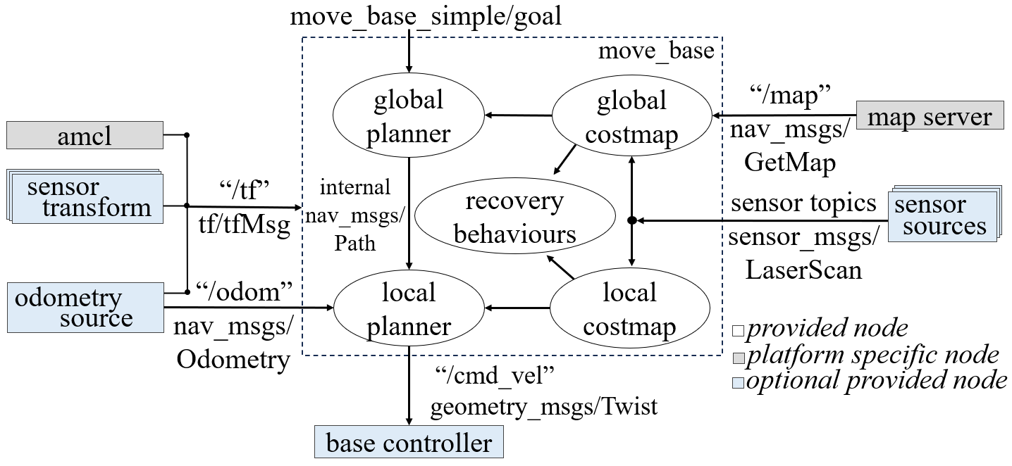
Figure 4: Navigation stack block diagram [1]

The ROS framework provides the Navigation Stack, a collection of packages for mobile robot navigation, handling localization, trajectory planning, and control signal generation. At its core, the navigation stack takes odometry and sensor data as inputs, producing velocity commands for robotic drive. Figure 4 illustrates the stack's main blocks and information flow. Inputs and outputs involve sensor sources, sensor transforms, odometry sources, and a base controller.

The light blue components in the figure indicate crucial input generators and output interpreters, comprising sensor sources for laser scan readings, sensor transforms for coordinate frame conversions, odometry sources for robot states, and a base controller for differential wheel commands. Grey blocks are optional, and white internal nodes manage sensor data, target positions, and control signals, ensuring proper ROS message structure within the paradigm. The navigation stack's internal nodes handle input data, implementing global and local mappings for planned trajectories and obstacle avoidance, all adhering to the ROS message typing.

D. Software architecture

This research makes significant contributions by introducing ROS support for the Sphero RVR and designing an architecture for the navigation process. This architecture integrates data acquisition, data fusion, mapping, localization, and control.

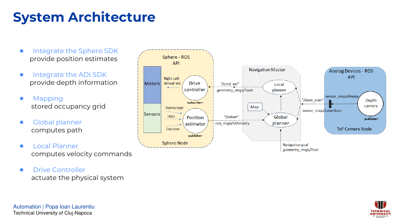
The robotic platforms can be characterized as distributed and modular system, with processing being run on the robot's onboard devices, as well as the camera module. All nodes are coordinated by a large navigation node implemented on the Jetson Nano board. The overall flow of data between the main processes can be observed in Figure 5.

Block Diagram

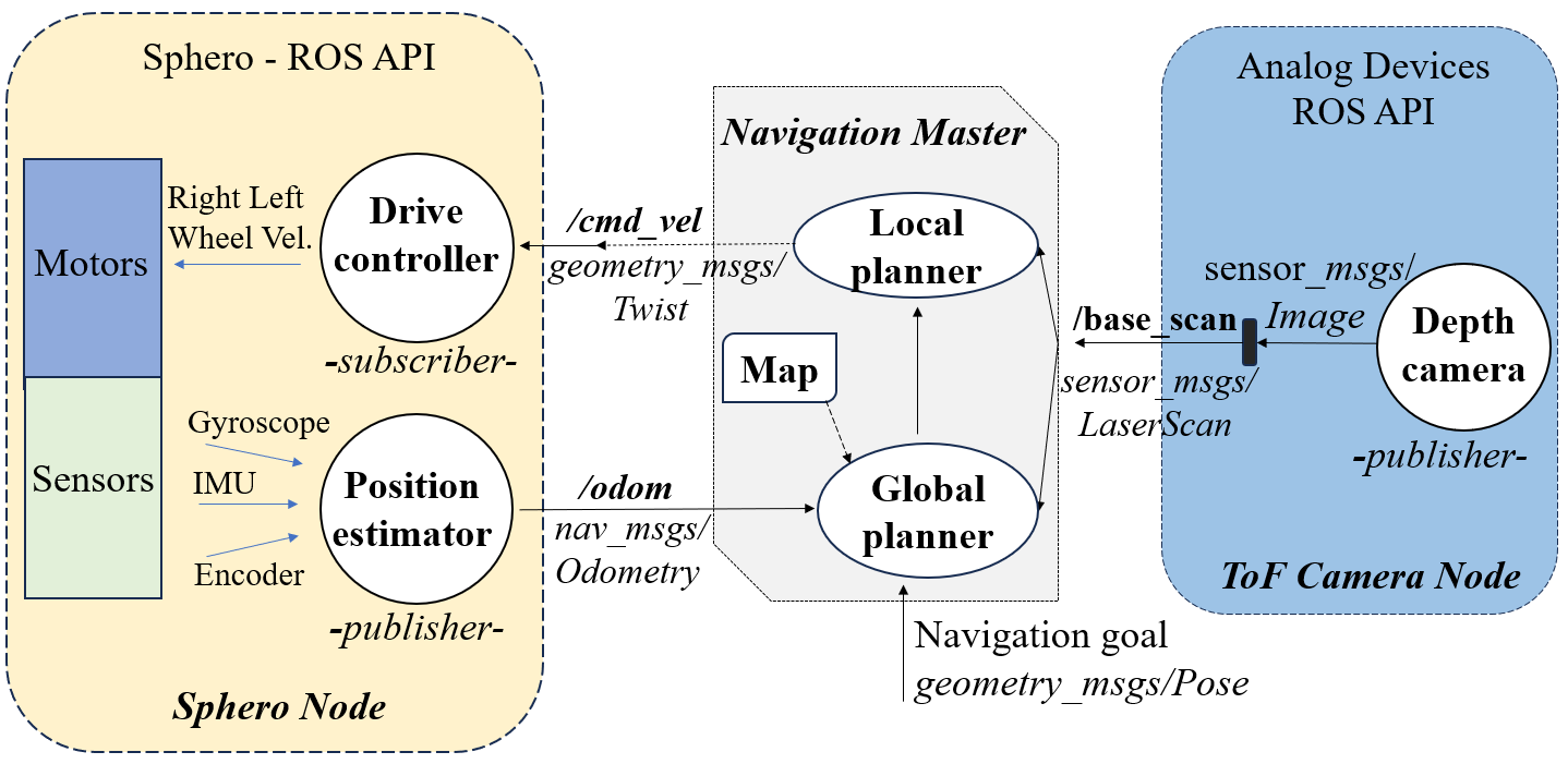
Figure 5: Robotic platform block diagram

The robot node integrates the SDK driver and the onboard sensors into a single process. It publishes the fused position data for the navigation master and subscribes to the same master node for velocity commands, which are decoded into voltage signals for the motor wheels. The camera node uses ROS bindings to extract depth data form the integrated circuit and publishes them in the form of 2D LaserScan. Those scans are used for mapping as well as real-time localization.

Key elements in the navigation master node are the local and global planners. The global planner utilizes the static map, initial and target poses to generate a trajectory. In contrast, the local planner assesses viability along the planned path, generating stable velocity commands for the robot.

E. Mapping. Localization. Navigation

The II chapter introduced the Kalman filter for data fusion in localization. However, it struggles with non-Gaussian noise in position or depth sensor measurements.

Another commonly used estimator for localization is the particle filter, or Monte Carlo Localization. It relies on mapping grids and laser scanning data to estimate distance. With thousands of randomly distributed particles, the algorithm converges to determine the robot's position [20]. The main parameters we are interested in are: the belief (a measure of trust in a certain location) bel(xt) represented as a sequence of particles Xt = (x1, x2, ..xt) and the distribution by which we generate the particles at each step, p(x0).

Summarizing the steps above, according to [21]: An initial sampling of particles using uniform distribution, followed by weight assignment according to current laser sensor readings, resampling of particles according to the new distribution, moving the particle cloud according to the dead-reckoning model, and repeating the steps until the distribution centers around a best location estimate.

Real systems aim to optimize computational resources, leading to the adoption of Adaptive Monte Carlo Localization (AMCL) in navigation tasks. AMCL adapts to changing distributions by reducing particle generation as the distribution narrows. Research has explored particle filter localization parameters and their impact through consistent experiments. Results demonstrate the relationship between parameters and localization response [22]. In simulations, AMCL proves effective in localizing and navigating an Automated Guided Vehicle in both static and dynamic environments, ensuring successful goal achievement [23].

Mapping 1 Mapping 2 Mapping 3
Environment Final Map Robot

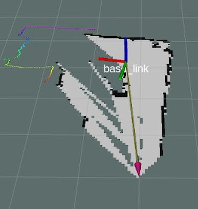
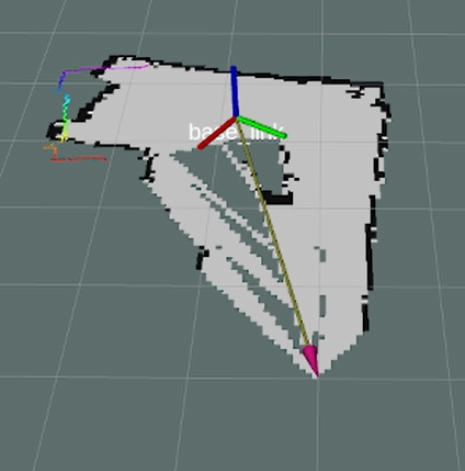
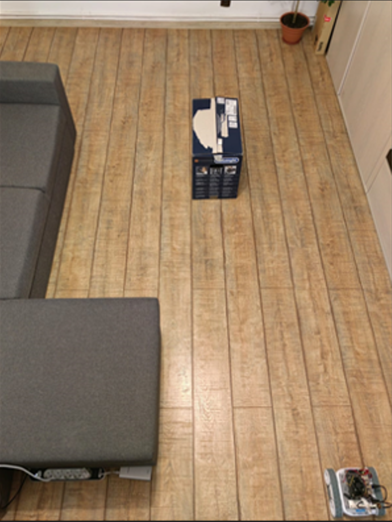
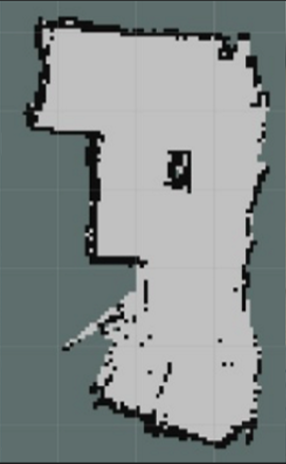
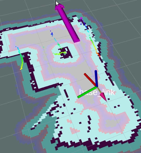
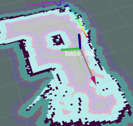
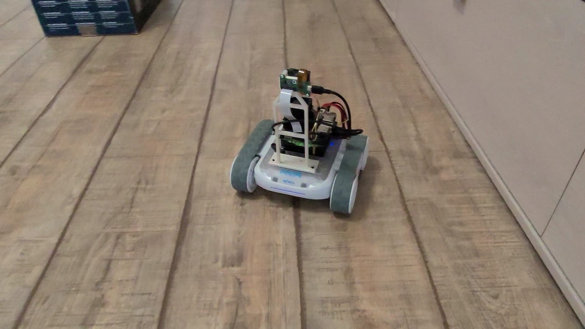
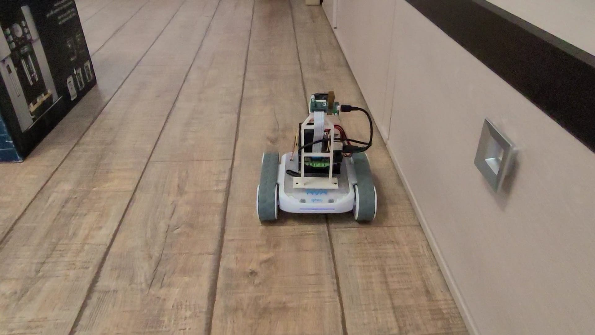
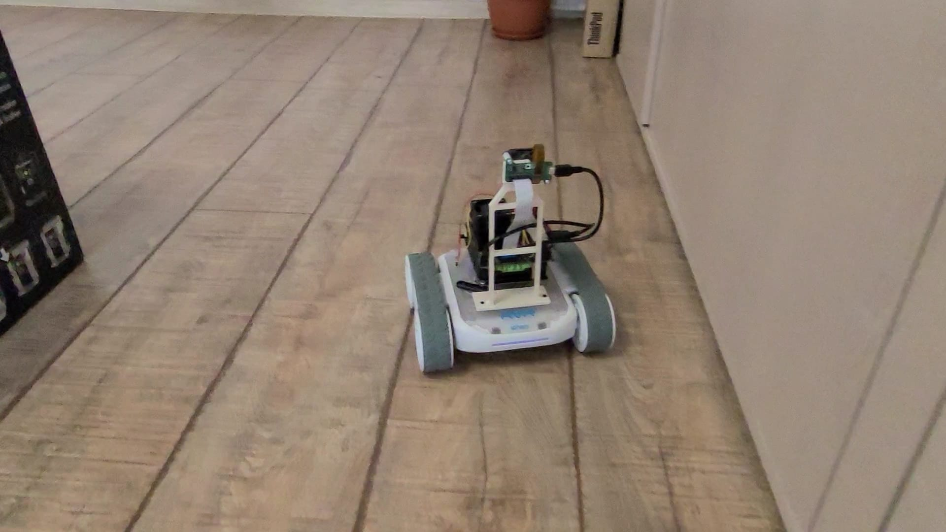
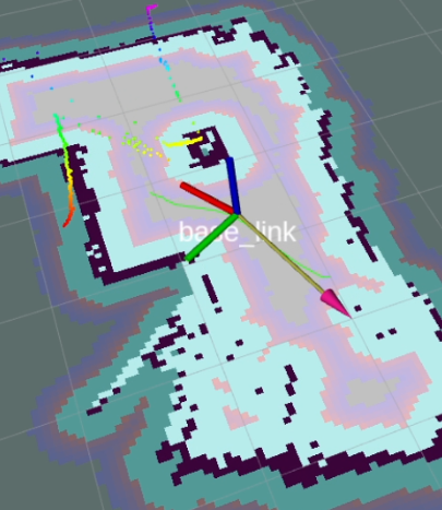
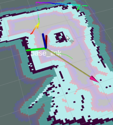
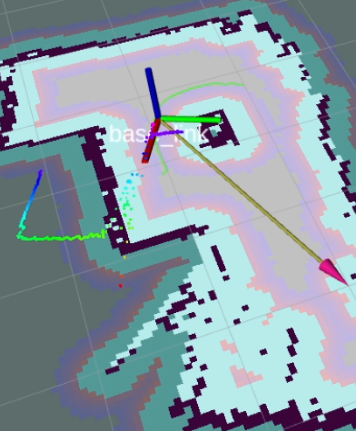
Figure 6: Indoor environment and incremental mapping

Initial development occurred in a ROS virtual environment, a platform that offers nodes for simulating environmental features, sensor streaming, and drive control. The stageros process encapsulates the 2D environment using a world file, specifying details about the simulated robot and mapped obstacles. A notable feature is the sensor simulation, where the node publishes data based on provided models.

Real environment mapping can be achieved through the gmapping ROS package, utilizing the high frame rates from camera sensors (30 fps). A reliable pose estimate from IMU and encoders allows the usage of the gmapping node in simulation environments. After creating an odometry source by fusing sensor data, the gmapping node subscribes to information from "/odom" and "/scan" topics, generating the map. Sequences of the mapping process can seen in Figure 6.

AMCL 1 AMCL 2 AMCL 3

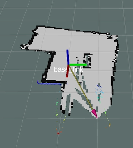
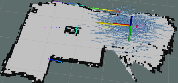
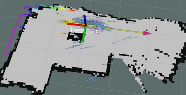
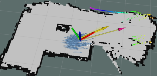
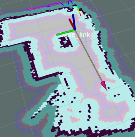
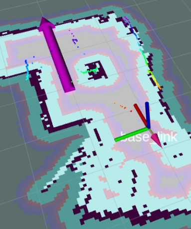
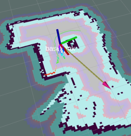
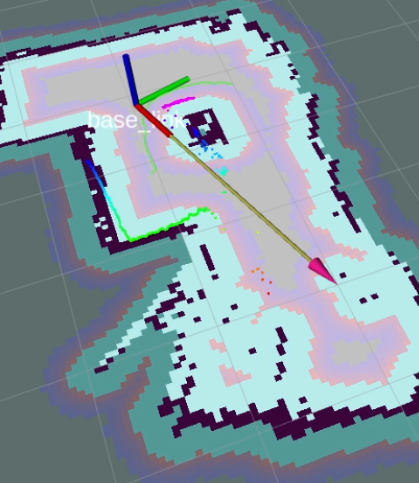
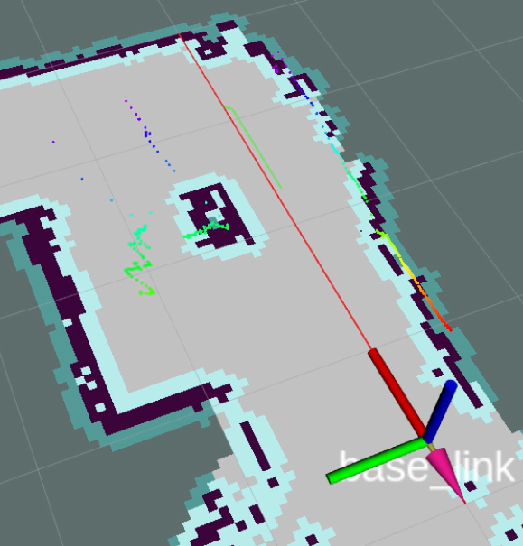
Figure 7: Pose estimates using the amcl particle filter

Continuous pose estimates are crucial for effective navigation, even with a constructed map. While the navigation node generates the path and initial velocity commands, lack of continuous updates can lead to control signal saturation or collisions. Relative robot position is determined through dead-reckoning, utilizing the odometer node to fuse sensor data into a nav_msgs/Odometry message. The extracted data includes IMU orientation, encoder-locator position estimates, gyroscope angular velocity, and accelerometer linear velocities. Rotation in inertial frames is addressed by remapping coordinates. Strategies like Adaptive Monte Carlo can enhance the relative positioning system, using the amcl package, as seen in Figure 7. This system employs odometry, map, and laser scans, with adjustments for potential delays. The estimated position converges as the robot explores, aligning with dead-reckoning effectiveness in small environments.

IV. Testing and Results

The testing procedure consists mainly on observing the robot performance in a previously mapped room by comparing the visual input in the tracking window with the real moving trajectory of the robot. The three main challenges for the navigation testing were: (a) travel a free area of the map, mostly in a straight line, (b) curved trajectories, object detection and avoidance, (c) recovery maneuvers.

(a)

(b)

(c)

Figure 8: ROS rviz: (a) Initial and target poses; (b) Move by inflation radius; (c) Approaching goal pose vs Real robot

The a) moving in free space challenge, considering the mapped objects and the buffer zones associated with them for maintaining a safe distance, see Figure 8.

(a)

(b)

(c)

Figure 9: ROS rviz: (a) Initial and target poses; (b) Object detection. Steering; (c) Approach goal with error vs Real robot

The b) avoiding objects challenge, planning a curved trajectory to avoid a mapped object and using the sensor data to perform the steering action in real time, see Figure 9.

Note that higher values set on the goal tolerance affect the final orientation of the robot, but these errors are acceptable when compared to the effects of saturated control signals on the mechanic drive. We trade accuracy for a smoother control process, which is often more desirable in mobile robot applications. Better collision avoidance performances can be obtained by increasing the inflation radius, however decreasing the confidence on paths when moving via tight hallways.

(a)

(b)

(c)

Figure 10: ROS rviz: (a) Collision with box; (b) Start recovery. Move back; (c) Avoid object. Steering vs Real robot

The c) recovery action challenge, observing the behavior of the robot after collisions, see Figure 10.

Considering that the pose estimates visualized in the previous figure are affected by noise, we can design an experiment to see how does the position of the robot actually change when moving on a straight line considered along the X axis with length 3 m. The experiment design in illustrated in Figure 11.

(a) Physical setup

(b) ROS setup and test process

Figure 11: Testing of heading error on straight line

Table I: Experimental data - robot moving straight line

DirectionMSE (cm)Ratio to hall width (%)Readings
Positive X0.6371.8235
Negative X0.7122.0337

The hall the robot traverses is 70 cm wide, with 35 cm on each side. The percent ratio is calculated based on these 35 cm values, where a maximum drift on either side equals 100% steering error. The readings column denotes the number of readings received by the odometry system at a rate of 1 Hz. The initial row was filled by navigating the robot along a straight line, moving forward along the positive X axis, then reversing direction. Drift errors amounting to approximately 2% of the hall's width suggest a highly dependable trajectory, as shown by the green path in Figure 11, in comparison to the reference red line, as well as excellent position control.

V. Conclusions

In conclusion, this research marks a significant contribution in exploring mobile robot control and navigation through the integration of cutting-edge technologies. The solution involves the development of ROS support for the Sphero RVR, providing odometry data for the navigation system and the incorporation of Analog Devices Time-of-Flight technology. Calibration processes, coupled with the utilization of depth data for laser scanning, mapping, and particle filter localization, exemplify the integration and functioning the ToF module. Testing scenarios shown above underscore the robustness and efficacy of the implemented system.

The versatility of this research extends into diverse use cases, including surveillance, security, industrial automation, transport, delivery, education, and research, paving the way for future study in the field of mobile robotics.

References

  1. M. Quigley, K. Conley, B. Gerkey, J. Faust, T. Foote, J. Leibs, R. Wheeler, A. Y. Ng et al., "ROS: An Open-Source Robot Operating System," in ICRA Workshop on Open Source Software, vol. 3, no. 3.2. Kobe, Japan, 2009, p. 5.
  2. F. Rubio, F. Valero, and C. Llopis-Albert, "A Review of Mobile Robots: Concepts, Methods, Theoretical Framework, and Applications," International Journal of Advanced Robotic Systems, vol. 16, no. 2, pp. 2,3,5, 2019.
  3. M. Ben-Ari and F. Mondada, Elements of Robotics. Springer Nature, 2017.
  4. S. G. Tzafestas, "Mobile Robot Control and Navigation: A Global Overview," Journal of Intelligent & Robotic Systems, vol. 91, pp. 35-58, 2018.
  5. T. Yang, Y. Li, C. Zhao, D. Yao, G. Chen, L. Sun, T. Krajnik, and Z. Yan, "3D ToF LiDAR in Mobile Robotics: A Review," ArXiv Preprint ArXiv:2202.11025, 2022.
  6. L. Li et al., "Time-of-Flight Camera - An introduction," Technical White Paper, no. SLOA190B, 2014.
  7. N. O'Sullivan, Paul und Le Dortz, "Time of Flight System Design - Part 1: System Overview," in Analog Dialogue, Vol. 55, No. 3. Analog Devices, 2021.
  8. S. L. X. Francis, S. G. Anavatti, M. Garratt, and H. Shim, "A ToF Camera as a 3D Vision Sensor for Autonomous Mobile Robotics," International Journal of Advanced Robotic Systems, vol. 12, no. 11, p. 156, 2015.
  9. W. Jo, J. Kim, R. Wang, J. Pan, R. K. Senthilkumaran, and B.-C. Min, "SMARTmBOT: A ROS2-Based Low-Cost and Open-Source Mobile Robot Platform," ArXiv Preprint ArXiv:2203.08903, 2022.
  10. X.-B. Jin, T.-L. Su, J.-L. Kong, Y.-T. Bai, B.-B. Miao, and C. Dou, "State-of-the-Art Mobile Intelligence: Enabling Robots to Move like Humans by Estimating Mobility with Artificial Intelligence," Applied Sciences, vol. 8, no. 3, p. 379, 2018.
  11. F. Gul, W. Rahiman, and S. S. Nazli Alhady, "A Comprehensive Study for Robot Navigation Techniques," Cogent Engineering, vol. 6, no. 1, p. 1632046, 2019.
  12. A. M. Rezende, G. P. Junior, R. Fernandes, V. R. Miranda, H. Azpurua, G. Pessin, and G. M. Freitas, "Indoor Localization and Navigation Control Strategies for a Mobile Robot Designed to Inspect Confined Environments," in 2020 IEEE 16th International Conference on Automation Science and Engineering (CASE). IEEE, 2020, pp. 1427-1433.
  13. B. Patle, G. Babu L, A. Pandey, D. Parhi, and A. Jagadeesh, "A Review: On Path Planning Strategies for Navigation of Mobile Robot," Defence Technology, vol. 15, no. 4, pp. 582-606, 2019.
  14. S. Faria, J. Lima, and P. Costa, "Sensor Fusion for Mobile Robot Localization Using Extended Kalman Filter, UWB ToF and Aruco Markers," in Optimization, Learning Algorithms and Applications: First International Conference, OL2A 2021, Braganca, Portugal, July 19-21, 2021, Revised Selected Papers 1. Springer, 2021, pp. 235-250.
  15. M. Yekkehfallah, M. Yang, Z. Cai, L. Li, and C. Wang, "Accurate 3D Localization Using RGB-ToF Camera and IMU for Industrial Mobile Robots," Robotica, vol. 39, no. 10, pp. 1816-1833, 2021.
  16. K. Zhu and T. Zhang, "Deep Reinforcement Learning Based Mobile Robot Navigation: A Review," Tsinghua Science and Technology, vol. 26, no. 5, pp. 674-691, 2021.
  17. C. Wang, L. Meng, S. She, I. M. Mitchell, T. Li, F. Tung, W. Wan, M. Q.-H. Meng, and C. W. de Silva, "Autonomous Mobile Robot Navigation in Uneven and Unstructured Indoor Environments," in 2017 IEEE/RSJ International Conference on Intelligent Robots and Systems (IROS), 2017, pp. 109-116.
  18. M. Kegeleirs, R. Todesco, D. G. Ramos, G. L. Herranz, and M. Birattari, "Mercator: Hardware and Software Architecture for Experiments in Swarm SLAM," IRIDIA, Universite libre de Bruxelles, Brussels, Belgium, Tech. Rep. TR/IRIDIA/2022-012, 2022.
  19. T. Wang, Y. Wu, J. Liang, C. Han, J. Chen, and Q. Zhao, "Analysis and Experimental Kinematics of a Skid-Steering Wheeled Robot Based on a Laser Scanner Sensor," Sensors, vol. 15, no. 5, pp. 9681-9702, 2015.
  20. S. Thrun, "Probabilistic Robotics," Communications of the ACM, vol. 45, no. 3, pp. 52-57, 2002.
  21. S. Godsill, "Particle Filtering: The First 25 Years and Beyond," in ICASSP 2019-2019 IEEE International Conference on Acoustics, Speech and Signal Processing (ICASSP). IEEE, 2019, pp. 7760-7764.
  22. W. P. N. dos Reis, O. Morandin, and K. C. T. Vivaldini, "A Quantitative Study of Tuning ROS Adaptive Monte Carlo Localization Parameters and Their Effect on an AGV Localization," in 2019 19th International Conference on Advanced Robotics (ICAR). IEEE, 2019, pp. 302-307.
  23. D. Talwar and S. Jung, "Particle Filter-Based Localization of a Mobile Robot by Using a Single LiDAR Sensor under SLAM in ROS Environment," in 2019 19th international conference on control, automation and systems (ICCAS). IEEE, 2019, pp. 1112-1115.

1https://github.com/sphero-inc/sphero-sdk-raspberrypi-python
2ToF github repository: https://github.com/analogdevicesinc/aditof_sdk
3https://wiki.analog.com/resources/eval/user-guides/ad-96tof1-ebz/ug_jetson

BibTeX

@InProceedings{popa2024tofamr,
  author    = {Popa, Ioan Laurentiu and Tamas, Levente},
  booktitle = {2024 IEEE International Conference on Automation, Quality and Testing, Robotics (AQTR)},
  title     = {{Application of Time-of-Flight Technology for Mobile Robot Perception and Navigation}},
  year      = {2024},
  address   = {Cluj-Napoca, Romania},
  note      = {Student Forum Paper ID: 94},
}